


Star-delta contactor assemblies
With a star-delta combination that is already assembled in the performance range from 5.5 kW to 90 kW or as individual parts for customer assembly up to a performance class of 500 kW, we offer an affordable, space-saving, and highly available option for reliably starting asynchronous motors.
Star-delta contactor assemblies portfolio
Preassembled Performance
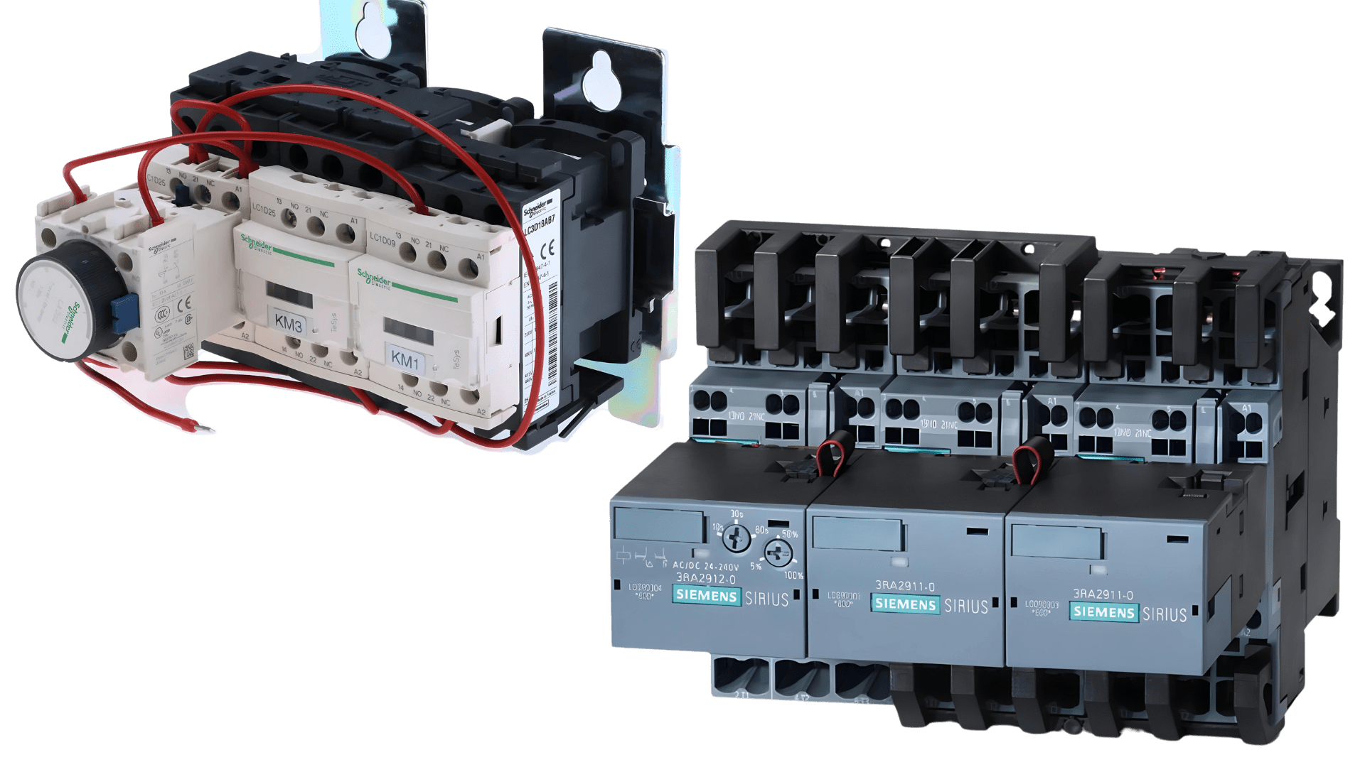
SIRIUS 3RA24 contactor assemblies for star-delta (wye-delta) starting, up to 90 kW
The 3RA24 contactor assemblies for star-delta (wye-delta) starting in sizes S00 to S3 can be ordered as follows:
- Fully wired and tested, with electrical and mechanical interlock
Benefits of preassembled star-delta combinations
- Space-saving
- Different connection technologies: screw terminals, spring-type terminals
- Only one order number

Customer assembly
Star-delta combinations for customer assembly
Naturally, we also offer you the option of ordering and assembling individual contactors in different performance classes from 5.5 kW to an output of 500 kW for star-delta combinations. As of a desired output of over 90 kW, the combinations of individual products must be assembled by the customer.

Highlights at a glance
Preferred circuitry
A star-delta (wye-delta) circuit reduces the starting current to 1/3 of the current compared to the current values for direct-on-line starting. However, when switching over from the star connection to the delta connection, the motor may be subjected to compensation processes, reinforced by an unfavorable constellation of line frequency and rotor field, which could result in higher current peaks than would be the case if the stationary motor were connected directly in the delta circuit.
An unfavorable scenario could lead to the following problems:
• Tripping of short-circuit protection devices,
• Welding or substantial contact erosion of the delta contactor,
• High dynamic load on the motor.
When connecting the motor using the preferred circuitry, the switchover currents from the star to the delta connection can be reduced.
This can avoid the problems mentioned above.


TeSys D – star delta starter
TeSys D pre-assembled star-delta starter, for motor control applications up to 11kW@400V in delta connection. Plate mounted starter, open version, composed of 3 contactors LC1D with 24V 50/60Hz AC coils, 1NC built-in auxiliary contact on star, a time-delay contact block 1-30 sec. For operating rates until 30 starts/hour, maximum starting time 30 sec. Compact assembly (144mm width), screw fixing. Equipped with pre-wired star delta power connections, and mechanical interlock, the use of a thermal overload relay (to be ordered separately) is strongly recommended. Green Premium compliant (RoHS/REACh).
Specifications
| Range | TeSys TeSys Deca |
|---|---|
| Product name | TeSys Deca |
| product or component type | Star delta starter |
| device short name | LC3D |
| contactor application | Motor control |
| Utilisation category | AC-3 |
| Device presentation | Pre-wired |
| Poles description | 3 x 3P |
| power pole contact composition | 3 x 3 NO |
| [Ue] rated operational voltage | Power circuit: <= 690 V AC 25…400 Hz |
| [Ie] rated operational current | 18 A (at <60 °C) at <= 440 V AC AC-3 for power circuit |
| Motor power kW | 11 kW at 220/230 V AC 50/60 Hz 22 kW at 415 V AC 50/60 Hz 22 kW at 440 V AC 50/60 Hz 18.5 kW at 380/400 V AC 50/60 Hz |
| Control circuit type | AC at 50/60 Hz |
| [Uc] control circuit voltage | 24 V AC 50/60 Hz |
| Auxiliary contact composition | 1 NC for KM1 star contactor |
| [Uimp] rated impulse withstand voltage | 6 kV conforming to IEC 60947 |
| Overvoltage category | III |
| [Ui] rated insulation voltage | Power circuit: 690 V conforming to IEC 60947-4-1 Power circuit: 600 V CSA certified Power circuit: 600 V UL certified Signalling circuit: 690 V conforming to IEC 60947-1 Signalling circuit: 600 V CSA certified Signalling circuit: 600 V UL certified |
| Electrical durability | 1.65 Mcycles 18 A AC-3 at Ue <= 440 V |
| safety cover | Protective cover |
| Interlocking type | Mechanical |
| Mounting support | Plate |
| Standards | IEC 60947-5-1 EN 60947-5-1 UL 508 CSA C22.2 No 14 IEC 60947-4-1 EN 60947-4-1 IEC 60335-1 |
| Product certifications | BV CSA RINA GOST UL GL LROS (Lloyds register of shipping) DNV CCC |
Complementary
| Connections – terminals | Control circuit: screw clamp terminals 1 1…4 mm² – cable stiffness: flexible without cable end Control circuit: screw clamp terminals 2 1…4 mm² – cable stiffness: flexible without cable end Control circuit: screw clamp terminals 1 1…4 mm² – cable stiffness: flexible with cable end Control circuit: screw clamp terminals 2 1…2.5 mm² – cable stiffness: flexible with cable end Control circuit: screw clamp terminals 1 1…4 mm² – cable stiffness: solid without cable end Control circuit: screw clamp terminals 2 1…4 mm² – cable stiffness: solid without cable end Power circuit: screw clamp terminals 1 1.5…6 mm² – cable stiffness: flexible without cable end Power circuit: screw clamp terminals 2 1.5…6 mm² – cable stiffness: flexible without cable end Power circuit: screw clamp terminals 1 1…6 mm² – cable stiffness: flexible with cable end Power circuit: screw clamp terminals 2 1…4 mm² – cable stiffness: flexible with cable end Power circuit: screw clamp terminals 1 1.5…6 mm² – cable stiffness: solid without cable end Power circuit: screw clamp terminals 2 1.5…6 mm² – cable stiffness: solid without cable end |
|---|---|
| Tightening torque | Power circuit: 1.7 N.m – on screw clamp terminals – with screwdriver flat Ø 6 mm Power circuit: 1.7 N.m – on screw clamp terminals – with screwdriver Philips No 2 Control circuit: 1.7 N.m – on screw clamp terminals – with screwdriver flat Ø 6 mm Control circuit: 1.7 N.m – on screw clamp terminals – with screwdriver Philips No 2 Power circuit: 1.7 N.m – on screw clamp terminals – with screwdriver pozidriv No 2 Control circuit: 1.7 N.m – on screw clamp terminals – with screwdriver pozidriv No 2 |
| Maximum operating rate | 30 cyc/h 60 °C |
| Starting time | 30 s |
| Coil technology | Without built-in suppressor module |
| Control circuit voltage limits | Drop-out: 0.3…0.6 Uc at 50/60 Hz (at <60 °C) Operational: 0.8…1.1 Uc at 50 Hz (at <60 °C) Operational: 0.85…1.1 Uc at 60 Hz (at <60 °C) |
| Inrush power in VA | 70 VA 60 Hz cos phi 0.75 (at 20 °C) 70 VA 50 Hz cos phi 0.75 (at 20 °C) |
| Hold-in power consumption in VA | 7.5 VA 60 Hz cos phi 0.3 (at 20 °C) 7 VA 50 Hz cos phi 0.3 (at 20 °C) |
| Heat dissipation | 2…3 W at 50/60 Hz |
| Auxiliary contacts type | Mechanically linked conforming to IEC 60947-5-1 3 x 1 NO + 1 NC Mirror contact conforming to IEC 60947-4-1 3 x 1 NC |
| Signalling circuit frequency | 25…400 Hz |
| Minimum switching current | 5 mA for signalling circuit |
| minimum switching voltage | 17 V for signalling circuit |
| Non-overlap time | 1.5 ms on de-energisation between NC and NO contact 1.5 ms on energisation between NC and NO contact |
| Width | 144 mm |
| Height | 124 mm |
| Depth | 143 mm |
| Net weight | 1.73 kg |
| Insulation resistance | > 10 MOhm for signalling circuit |
|---|---|
| IP degree of protection | IP20 front face conforming to IEC 60529 |
| Climatic withstand | Conforming to IACS E10 conforming to IEC 60947-1 Annex Q category D |
| Protective treatment | TH conforming to IEC 60068-2-30 |
| Pollution degree | 3 |
| Ambient air temperature for storage | -60…80 °C |
| Ambient air temperature for operation | -40…70 °C at Uc |
| Operating altitude | 3000 m without derating |
| Fire resistance | 850 °C conforming to IEC 60695-2-1 |
| Flame retardance | V1 conforming to UL 94 |
| Mechanical robustness | Vibrations contactor open: 2 Gn, 5…300 Hz Vibrations contactor closed: 4 Gn, 5…300 Hz Shocks contactor open: 10 Gn for 11 ms Shocks contactor closed: 15 Gn for 11 ms |
Sustainability
Green PremiumTM label is Schneider Electric’s commitment to delivering products with best-in-class environmental performance. Green Premium promises compliance with the latest regulations, transparency on environmental impacts, as well as circular and low-CO2 products.
Dimensions Drawings
LC3 | D09A | D12A | D18A | D32A | |
|---|---|---|---|---|---|
a | 143 | 143 | 144 | 165 | |
b | 26.5 | 26.5 | 26.5 | 32.5 | |
c | with LAD S | 139 | 139 | 139 | 145 |
with LAD S and sealing cover | 143 | 143 | 143 | 149 | |
Connections and Schema
NOTE: LC3 D09A to D18A: Mechanical interlock between KM3 and KM1.